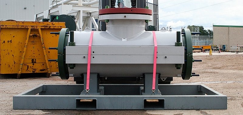
Hot Tap Clamp
Mechanical Hot Tap Clamp feature a dual seal arrangement which provides an annulus cavity to fully verify the seal integrity prior to hot tapping. Compression flanges mechanically actuate the seals and drive taper locks that grip the pipe, providing axial restraint.
The clamp components are compatible with a wide range of fluid types and flow conditions. Designed for ease of installation and minimal disruption to the pipework or system to which they are fitted. STATS can provide the complete service including clamp installation, hot tapping and BISEP line plugging. Completion plugs can also be provided to permanently isolate the flanged tee branch and enable the removal of the slab valve allowing a blind flange to be fitted to the mechanical clamp.
Key Features of the Hot Tap Clamp
The branch connection is designed with a customizable size and angle to suit specific application needs, thereby ensuring precise integration into various pipeline systems. Moreover, it is suitable for both hot tapping and BISEP line plugging, which makes it a versatile choice for different intervention methods. Additionally, the dual seal design, complete with an annulus test facility, enhances operational safety by enabling pressure verification between seals. To further enhance adaptability, structural locks and grout injection options are also available, allowing the solution to be tailored to specific project requirements.
Beyond its design flexibility, the system is compatible with a wide range of materials, including carbon steel, stainless steel, duplex, super duplex, and clad pipe, thus offering broad applicability across industries and environments. It is engineered to withstand temperature ranges from -40°C to 250°C, or as otherwise specified by the client. Furthermore, the unit can be supplied with either single or dual sealing configurations, using elastomeric or graphite sealing materials to best match the medium and operating conditions of the pipeline. Finally, it is rated for high working pressures up to and including ANSI 2500 (638 bar), covering all common pressure classes such as 300#, 400#, 600#, 900#, and 1500#, with additional customization available upon request.
Material Specification
Pipe Sizes | 1″ & Above |
Split Body Shell | SA / ASTM A 516 Gr. 70 ASTM A 106 GR A, B, C Seamless Pipe ASTM A516 Gr. 70 Steel Plate API 5L Gr B, X42, X46, X52, X56, X60, X65, X70 ASTM A36 ASTM A572 Gr42, Gr50, Gr55, Gr60, Gr65 ASTM A516 Gr55, Gr60, Gr65, Gr70 ASTM A537 Class 1, Class 2, Class 3 EN 10025 ASTM A216 WCC ASTM A352 LCC ASTM A216 WCB Any other as per client requirement. |
Body Flange (Stiffner) | ASTM A350 LF2 / ASME || SA350 LF2 ASTM A105 / ASME || SA105 Any other as per client requirement. |
Stud & Nut | ASTM A 193 Gr. B7, with A194 Gr 2H or as per client requirement Nuts. ASTM A 194 Gr2.2H, 2HM, 4, 7, 7M, 8, 8M ASTM A307 Gr A, B, C ASTM A320 Gr L7, L43 ASTM A325 Gr Type 1, Type 2, Type 3 Any other as per client requirement. Coating: Yellow Epoxy Polyamide, Standard or Marine Epoxy Galvanized, PTFE, Xylan Coated or any other as per client requirement |
Seals / Gaskets | NBR temperature range is from -20°C to +80°C Viton temperature range is from -20°C to +200°C Silicone, Kevlar, Hycar HNBR temperature range is from -20°C to +150°C Any other as per client requirement |
Vent Plug | SA / ASTM A 105 |
Lifting Plug | SA / ASTM A 516 Gr. 70 |
Sacrifical Anode | Zinc Alloy Any other as per client requirement. |
Hinges Assembly | SA / ASTM A516 Gr. 70 SA / ASTM A-325 ASTM A106 Gr A, B, C, Seamless Pipes ASTM A572 Gr42, Gr50, Gr55, Gr60, Gr65 ASTM A516 Gr55, Gr60, Gr65 ASTM A36 ASTM A537 Class 1, Class 2, Class 3 EN 10025 – S235, S275, S355, S540 ASTM A 193 Gr. B7, with A194 Gr 2H Nuts. ASTM A 194 Gr2.2H, 2HM, 4, 7, 7M, 8, 8M ASTM A307 Gr A, B, C ASTM A320 Gr L7, L43 ASTM A325 Gr Type 1,Type 2,Type 3 Any other as per client requirement. |
Design Code | ASME SEC VIII API 6H ANSI B31.3 ANSI B31.4 ANSI B31.8 |
Design standards | API SPEC 6H, Specification on End Closures, Connectors and Swivels API SPEC 5L, Specification for Line Pipe ASME Pressure Vessel Code, Section VIII ASME/ANSI B18.2.1, Square and Hex Bolts and Screw Inch Series |
Design Pressure | 300#, 400#, 600#, 900#, 1500#, 2500# Any other as per client requirement. |
Hydrotest Pressure | 1.3 X Design Pressure 1.5 X Design Pressure Any other as per client requirement. |
Design Temperature | 0 to 212°F Any other as per client requirement. |
Design Temperature | Yellow Epoxy Polyamide, Standard or Marine Epoxy, Galvanized, PTFE, Xylan Coated Any other as per client requirement. |
Sealing Length | As per client requirement. |
Mechanical Hot Tap Clamp Applications
Mechanical hot tap clamps are widely utilized in various subsea and topside pipeline operations due to their versatility and reliability. To begin with, one of the key applications is for tie-ins or re-routing of subsea pipeline infrastructure, where maintaining continuous flow is critical. In addition, they serve as essential access points during subsea pipeline repair, enabling the deployment of technologies such as BISEP, a double block and bleed line plugging system.
Furthermore, mechanical hot tap clamps are instrumental in creating safe and efficient connections for live pipeline branching, emergency leak containment, and temporary bypass systems. They also play a vital role in installing sensors or monitoring equipment without disrupting ongoing operations. As a result, these clamps are a crucial component in both planned modifications and urgent interventions, providing a non-intrusive solution for maintaining pipeline integrity and operational uptime in demanding environments.
Applicable International Standards
The design, engineering and supply of the fire tubes (two off) shall conform wherever applicable, and unless otherwise specified & agreed, to appropriate API, ASTM, ANSI, ASME or equivalent standards / codes and also to internationally-accepted standards and practices. All Standards and Codes followed for the Design shall be of latest version/ edition.
API RP 1160 API 6H/ API 6X/ API 5L | Managing System Integrity of Hydrocarbon Liquid Pipelines |
ASME B31.3, ASME B31.4, ASME B31.8 | Pipeline Transportation System for Liquids |
ASME Section IX | Specification for Welding and Brazing Qualifications |
ASME Section V | Non-Destructive Examination |
ASME Section II Part C | Specification for Welding Rods, Electrodes and Filler Materials |
ASME Section VIII, Div 1 | Rules for Construction of Pressure vessels |
ASTM E 94 | Standard guide for Radiographic examinations |
ASTM E709 | Standard guide for Magnetic Particle examination |
ASTM E1003 | Standard test method for Hydrostatic Leak testing |
Testing & Certifications
- Non-destructive testing (NDT)
- 100% magnetic particle inspection (MPI) for stiffener to shell weld (fillet)
- 100% ultrasonic testing of vent plug welds
- 100% MPI fo hinge welds
- Hydro Test as per ASME Secion VIII Div. 1 clause UG-99 Dimensional & Visual
- Hardness
- Load Testing of Hook & Hinge
- Painting Inspection
- Any other as per client requirement.
Contact for Pipe repaire Leak.
For more details on the products contact us.
Half Pipe Sleeve, Half Repair Pipe Sleeve, Pre-Stressed Metallic Sleeve.